|
||||||
 Constant
Current Source Module Constant
Current Source Module
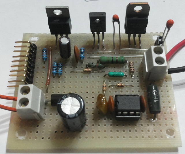
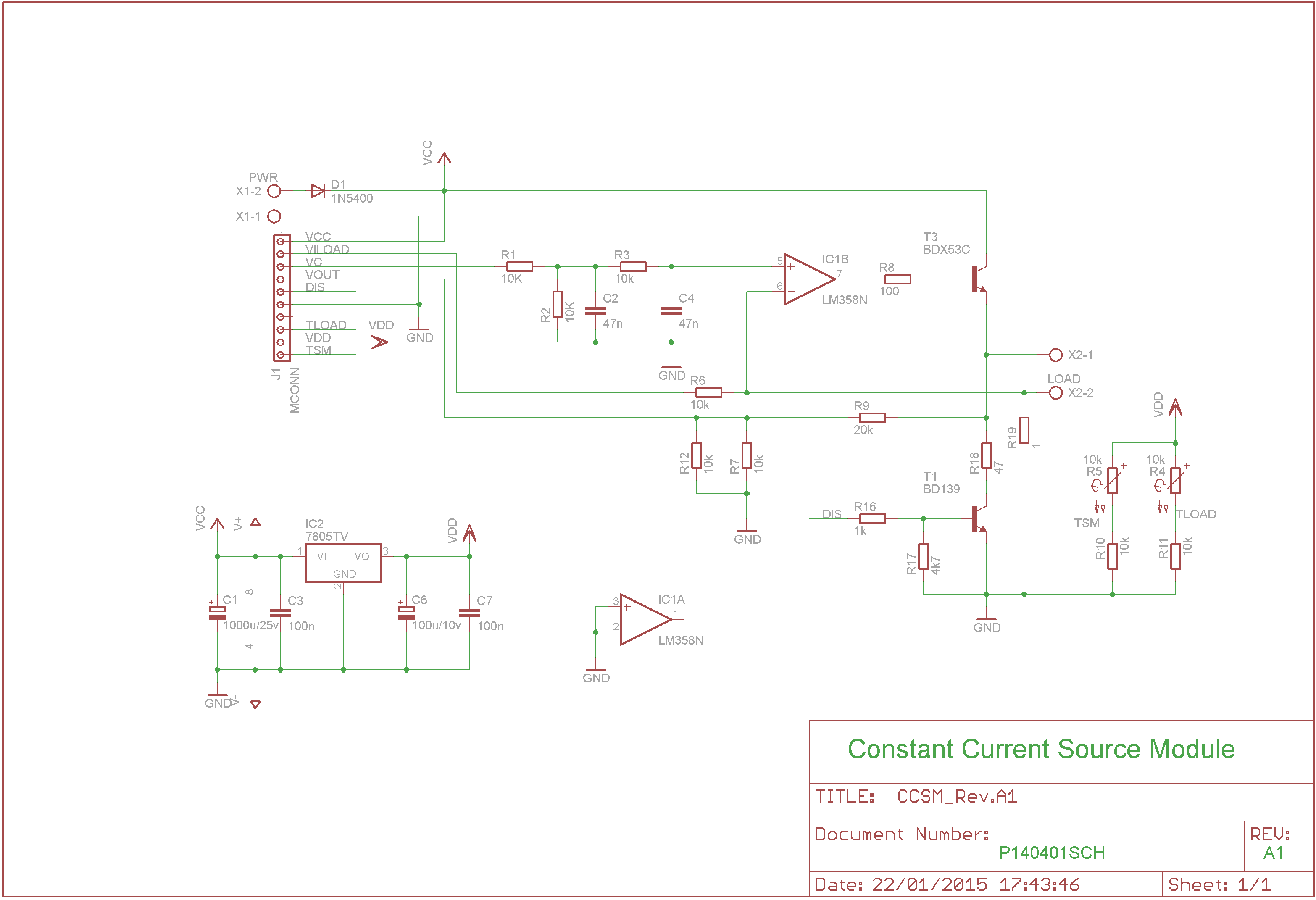
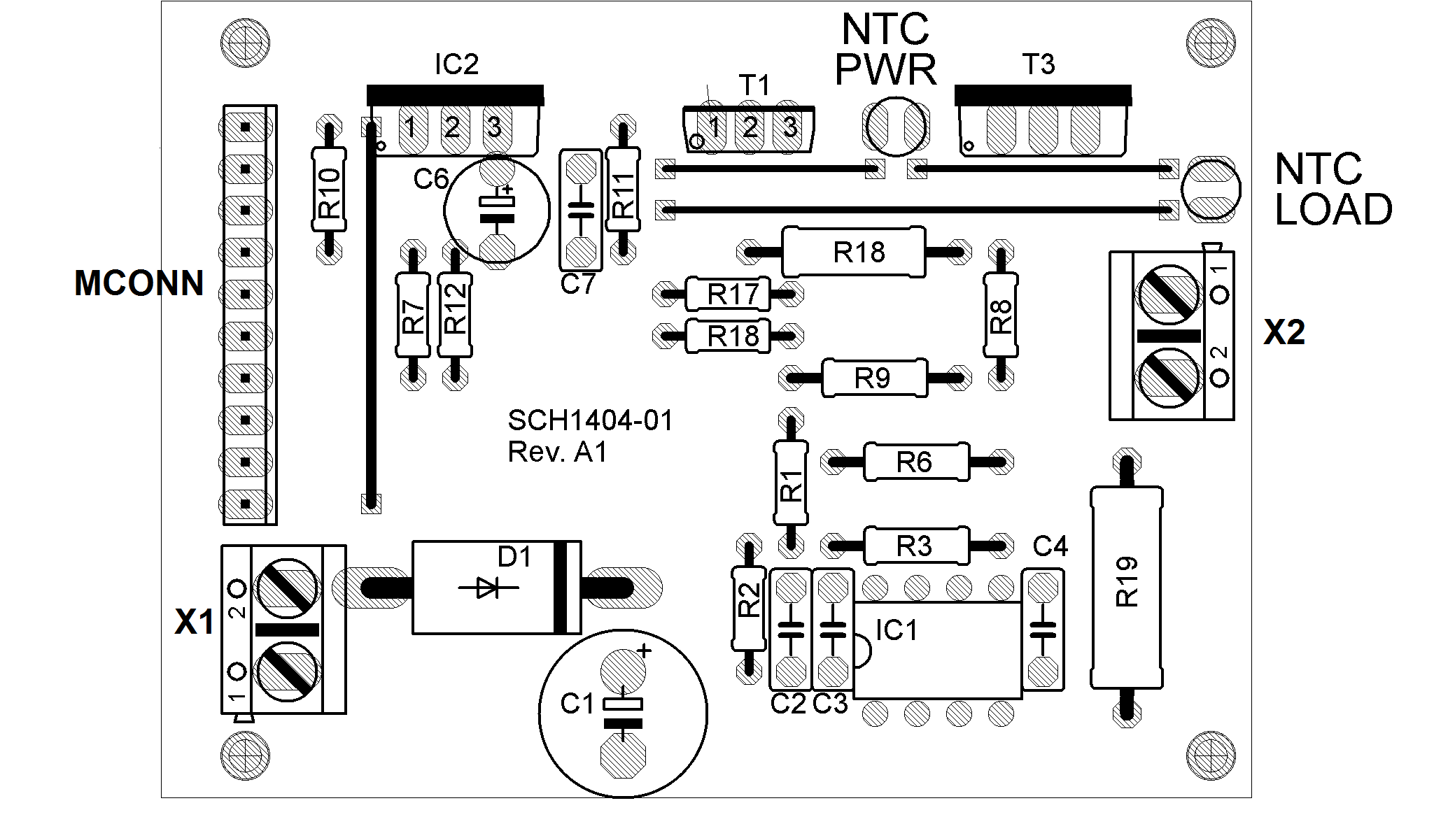
This module generates a constant current proportional to a voltage provided at the input. The module can be used as a battery charger, to drive the LEDs, or for any other use where it is necessary to provide a constant current. The module has an internal load and different test points to monitor the status of the load and the power stage. The relationship between output current and input voltage is 0.5 ie 500ma output for 1Volt input. The control voltage can be either continuous, in the range between 0 and 5 volts, or a TTL signal with a fixed frequency and variable duty cycle. In this case the output current is directly proportional to the duty cycle, ie the 1% value corresponds approximately 25mA while the value of 99% of 2470 mA. The load has three sensing circuits; one for the voltage (which is the one across the load divided by 5), one for the current (which provides a voltage proportional to the current flowing in the load) and one for the temperature. This is monitored by a thermistor. Another thermistor is used to monitor the temperature of the power stage. The thermistors are placed in a divider, whose output voltage varies with the temperature. All signals are referenced to ground and sensing are in the range between 0 and 5 volts (Range compatible with most of the ADC included in microcontrollers) .. The internal load is constituted by a resistor 47ohm and can be enabled and disabled via a TTL signal. The module has a voltage regulator, which provides a voltage of 5volts. All the control signals and monitors are reported to a connector. The module can be powered with a voltage between 9 and 25volts. the power supply must provide at least 3 Amps. Construction whitin the links below are available all the information for the construction of the module. capacitors are all ceramic 63volts, the resistors are all 1/4 watt except where indicated. A special note deserve the thermistors. The thermistor type must be chosen according to the way in which one wants to control the temperature. NTC with the output voltage from the sensing circuit decreases with increasing temperature, with the PTC is the inverse. In any case, the thermistor that controls the power stage must be fixed to the heat sink of the power transistor (T3), while the other thermistor must be in contact with the load. The temperature sensing circuits are not strictly necessary and in case, you are sure that the temperatures do not reach high values may be omitted. Pinout of the module The figure 1 shows the module pinout. The connections are :
 Figure 1: module pinout |
||||||
|
The
material contained in this web site is provided "AS IS" without
warranty of any kind. The author is not responsible for direct or
indirect damages, accidents or others problems cause by the use of
information contained in this web site. All the product names, logos
and trademarks belong to the respective owners. The
use and
distribution of the material contents in this site is free with the
condition to summon the source. The commercial use of the web
site
materials is forbidden without the written authorization of the web
site author.
|

