|
|||||
 Demoboard with
PIC18F2550 Demoboard with
PIC18F2550DEMO2550
is a module based on
PIC18F2550, that enables the development and testing of HW/SW
applications, in a simple and quick way.
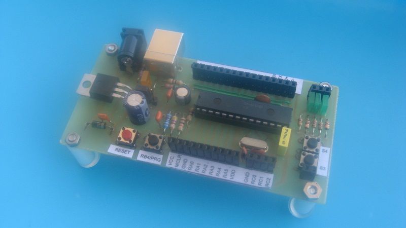
Choosing the PIC was motivated by the presence, within it, a USB interface that allows to program the component and to communicate with it. All the necessary software for programming via USB is provided by Microchip (c) and consists of a program to be loaded on the PIC (Bootloader) and a PC tool. The bootloader (for the beginners) is loaded into a reserved area of memory of the PIC. The program enter on action only after a specific power-up sequence and puts it in direct communication with the program running on the PC. At this point the PC we can load our application on the module. Details of the transaction will be clarified in the example given. For dialogue with the PIC even here we find solace in the Microchip that provides us with a basic infrastructure (Framework) ready to be integrated in our programs. The module has some simple adds-on (Leds, Buttons). They have been designed to make it completely independent and to facilitate the testing of simple solutions of interfacing with the outside world. Module Features
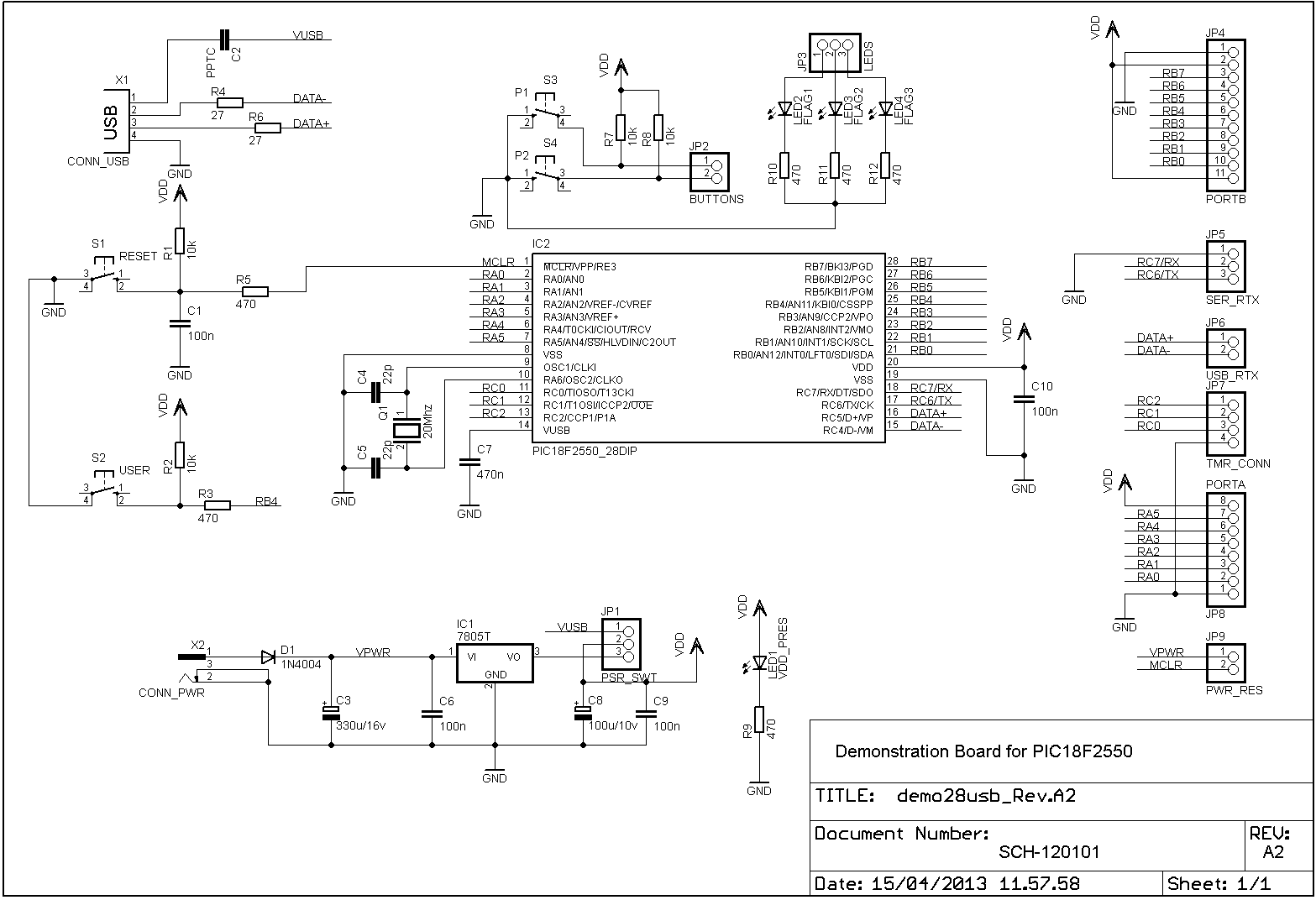
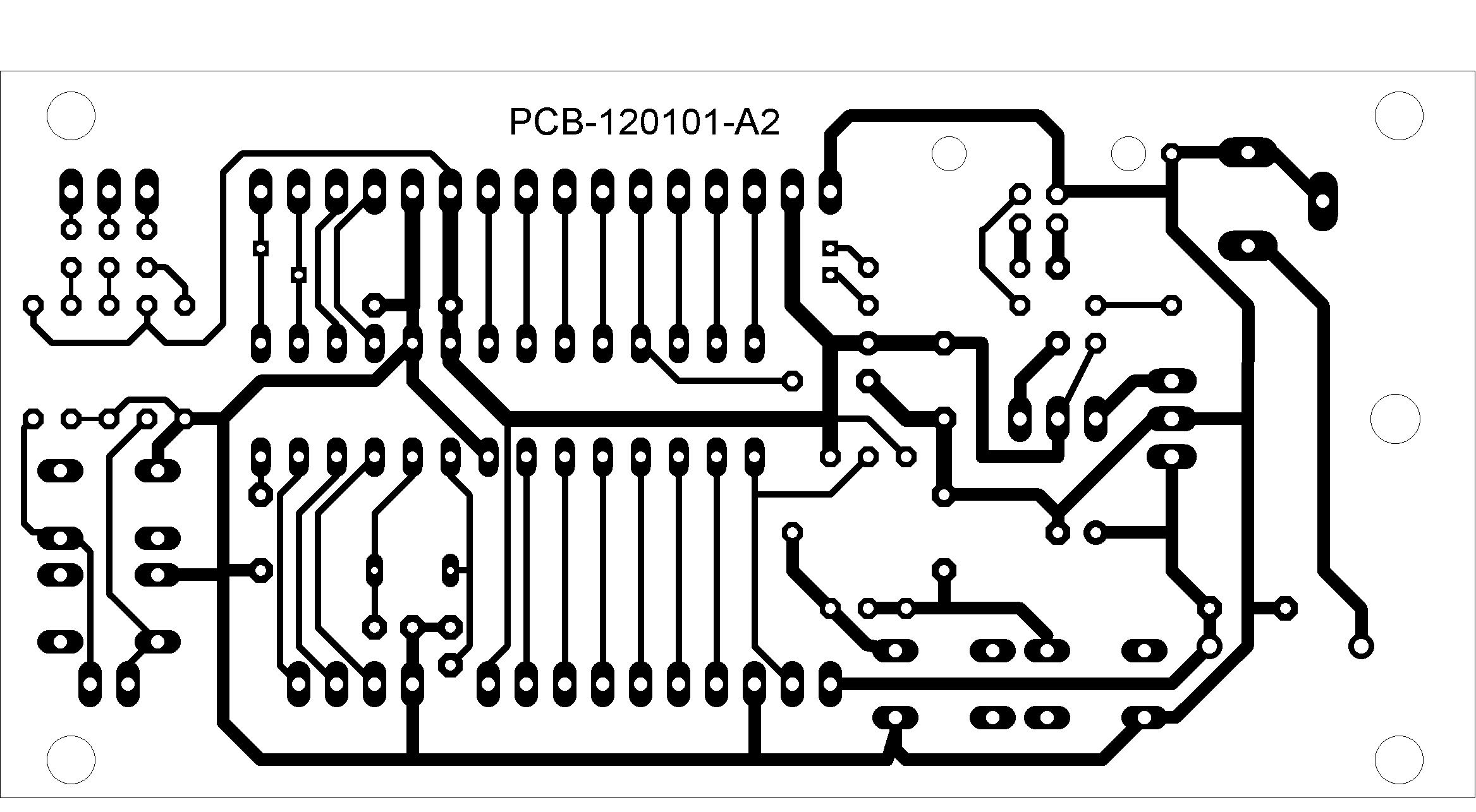
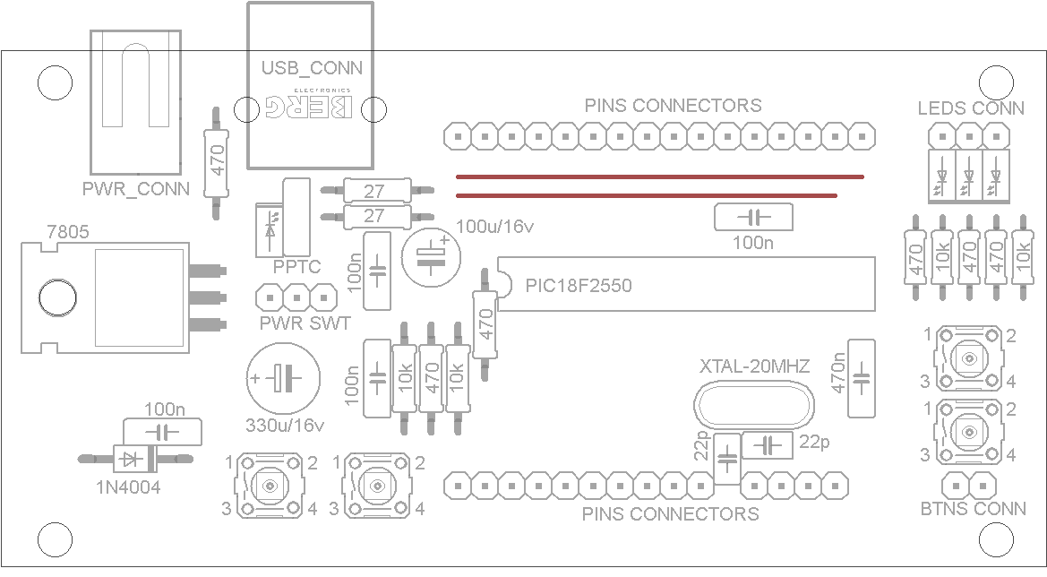
For the construction of the module you have to play the printed circuit board, taking the master from the link given below. The resistors are 1 / 8w to 5%. The component PPTC (represented in the circuit diagram from the capacitor C2) is an element ofprotection in case of extra currents. It really is not necessary, because the USB ports of the PC are already protected. In consequence of this, can be replaced with a jumper. PIC programming After the building and the electrical verification, the module must be programmed with the bootloader. The binary file is available at below link: Installations of the Software Development Enviroment and programming tool The software development environment to create applications for the module consists of two tool, the IDE and MPLAB C18 compiler. The tools are to be taken to the link below and installed in this order, ie before the IDE and then the compiler. For the use of the tools I refer to the documentation provided by Microchip. In Figure 1 there is the pinout of the module with all connections and controls for its use. The connections of the module are:
The controls of the module are:
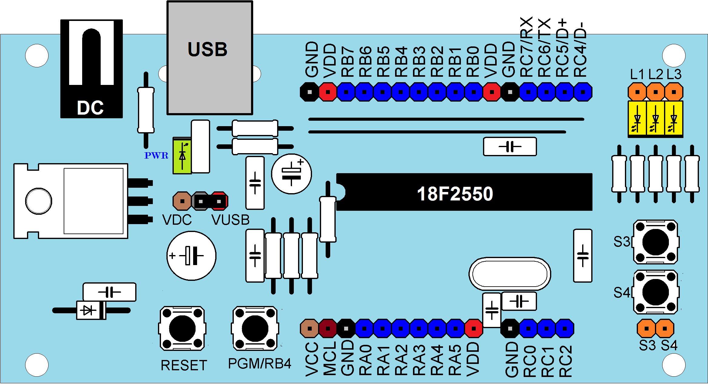 Figure 1: module pinout Use of the module To load an application on the module, you have to activate the loader mode, to do it, you must connect the module to a PC's USB port and perform the following steps:
Conclusions Although dedicated to PIC2550, nothing prevents you to mount the module other PICs, which have the same pinout. In this case, you lose the functionality of the USB and programming and must be carried out in any other way (Serial, programmer, etc). At the moment I have not foreseen this possibility and then I'm moving towards just basic applications for 2550. In particular, I'm adapting the framework of Microchip to develop the software in an easy and intuitive way |
|||||
|
The material contained in this web site is provided "AS IS" without warranty of any kind. The author is not responsible for direct or indirect damages, accidents or others problems cause by the use of information contained in this web site. All the product names, logos and trademarks belong to the respective owners. The use and distribuition of the material contents in this site is free with the condition to summon the source. The commercial use of the web site materials is forbidden without the written authorization of the web site author. |

